OSPF
1. OSPF intro
1.1. Unlike RIP
While RIP is easy enough to implement and use in small networks, it becomes a
problem if the network becomes larger.
The solution is the use of another protocol: OSPF
OSPF uses a different protocol than RIP, and to understand OSPF, a set
of concepts must be clear.
1.2. Link State and Distance Vector
For routing, there are two types of protocols:
-
Distance Vector
-
Link State
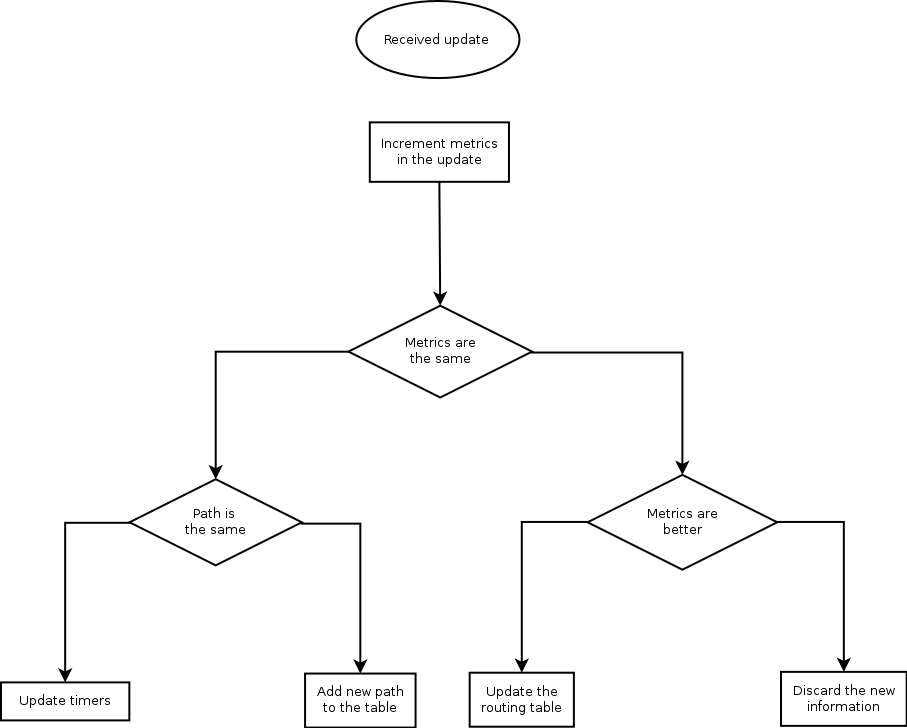
Distance vector protocols, like RIP, blurt out all the information that
they know, and listen to any updates that others send. The information is processed following the Bellman-Ford agorithm.
-
Increment the merics of the incoming routes.
-
Compare the incoming with the existing routing table
-
if the neighbour's information is better: replace the old entry in the routing table
-
if the information is worse, discard it
-
if it is the same, just reset some timers
-
If it has the same costs, but a different path, add it to the routing table anyway
Or,
In case of RIP, it is easy to understand step 1: the neighbour advertises its own
hop-count and to the neighbour, it is one hop extra.
Link State protocols, like OSPF, generally only generate messages when a topology
changes. They use multicasts in stead of broadcasts and they send their updates
reliably to other routers. The other routers will reply with an acknowledgement.
Link State routers will build a topology of the network, called the topology
table. To calculate the best route, Dijkstra's SPF algorithm is used.
Dijkstra's algorithm is a subject by itsself; I will content myself with a reference
to Packet Pushers.
1.3. Routers
All routers in an OSPF network must have a unique ID (that is: unique in
the OSPF network. The router ID is chosen according to one of the following criteria:
-
Manually defined
-
The highest IP address on the router’s active loopback interfaces
-
If no loopback interface exists with an IP address, the highest IP address on its active interfaces
Routers on the borders of areas and Autonomous systems have special names:
|
ABR
| Area Border Router: a router that is on the border of an area | |
|
ASBR
| Autonomoues System Border Router: a router that is on the border of tha autonomous system | |
|
DR
| Designated Router: for routers connected to a multi-access network, the router to which the LSAs are sent. | |
|
BDR
| Backup Designated Router |
Routers maintain contact with adjacent routers by sendin HELLO messages.
1.4. Link state advertisements (LSA)
OSPF uses Link Stata advertisements to communicate the link state between routers. The
most common LSA types are:
|
Type 1
| Generated by every router for each link that belongs to an area. They are flooded only inside of area to which they belong. Link ID of this LSA is the Router ID of the router that generated it. | |
|
Type 2
| Generated by Designated Router (DR) for multiaccess networks and describe the routers that are connected to that segment. They are sent inside the area to which the network segment belong. The Link ID is the interface ip address of the Designated Router which describe that particular segment. | |
|
Type 3
| Generated by Area Border Routers (ABRs). In type 3 LSAs are advertised networks from an area to the rest of the areas in AS. The link-state id used by this LSA is the network number advertised | |
|
Type 4
| Generated by ABRs, this type of LSA contain routes to ASBRs. Link id used is router ID of the ASBR described. Are not flooded in stub areas. | |
|
Type 5
| Autonomous system external LSAs are generated by ASBRs and contain routes to networks that are external to current AS. Link-state ID is network number advertised in LSA. Type 5 LSAs are not flooded inside any stub areas | |
|
Type 7
| Allow injection of external routes throug Not-so-Stubby-Areas (NSSA) (more on that later) |
1.5. Areas, Autonomous systems
An Autonomous system is a part of the network that is under control of a single
entity. IANA keeps a list of Autonomous systems that are publicly accessible, but
as long as you don't connect to the Internet, you can use private numbers.
IANA has reserved, for Private Use, a contiguous block of 1023 Autonomous
System numbers from the “16-bit Autonomous System Numbers” registry,
namely 64512 – 65534 inclusive.
IANA has also reserved, for Private Use, a contiguous block of 94,967,295
Autonomous System numbers from the “32-bit Autonomous System Numbers”
registry, namely 4200000000 – 4294967294 inclusive.
OSPF implements a two-level hierachy for areas:
-
Area 0, which is the backbone
-
All other areas
In general, all other areas are connected to the backbone.
We have now seen two types of area:
-
backbone (area 0)
-
standard area
But OSPF is a bit more complicated than that. There are also
-
stub areas
-
totally stubby areas
-
not so stubby areas
and fairly stubby areas, extremely stubby areas, just a bit stubby areas, and ... No, I am
exagerating.
A stub area is an area through which or into which AS external advertisements are not flooded.
This means that you would only be able to access devices within the AS from this type
of area. This is done to reduce the size of the topology database.
Totaly stubby areas takes this one step further by not even allowing LSA type 3; they
are replaced by a default route.
Not So Stubby Areas allow external routes to be flooded within the area. These routes
are leaked into other areas. However, external routes from other areas within the AS
are not flooded into these areas.
You can view the area-types as whether they accept certain types of LSA:
Type 1
|
Type 2
|
Type 3
|
Type 4
|
Type 5
|
Type 7
|
|
Backbone
|
yes
|
yes
|
yes
|
yes
|
yes
|
no
|
Standard
|
yes
|
yes
|
yes
|
yes
|
yes
|
no
|
Stub area
|
yes
|
yes
|
yes
|
no
|
no
|
no
|
Totally Stubby
|
yes
|
yes
|
no
|
no
|
no
|
no
|
Not-so-stubby
|
yes
|
yes
|
yes
|
no
|
no
|
yes
|
2. Area 0 - the backbone
2.1. Basic network set-up
As discussed, we need an area 0 as backbone for our OSPF. We will be doing
a number of tests here, so we'll create back bone of 4 routers.
We'll use 3600 type routers and put two NM-4E cards in each of them.
We will use the card in slot 0 for the backbone, and the card in slot 1
for connecting the other areas.
We will be using 10.128.0.0/24 for the backbone. I am in general wastefull
in connecting routers in the test environments, using /24 for interconnection
networks, but this time, we'll do some proper calculations.
From
|
To
|
Network
|
Bits
|
Netmask
|
First
|
Last
|
Broadcast
|
R1
|
R2
|
10.128.0.0
|
/29
|
255.255.255.248
|
10.128.0.1
|
10.128.0.6
|
10.128.0.7
|
R2
|
R3
|
10.128.0.8
|
/29
|
255.255.255.248
|
10.128.0.9
|
10.128.0.14
|
10.128.0.15
|
R3
|
R4
|
10.128.0.16
|
/29
|
255.255.255.248
|
10.128.0.17
|
10.128.0.22
|
10.128.0.23
|
R4
|
R1
|
10.128.0.24
|
/29
|
255.255.255.248
|
10.128.0.25
|
10.128.0.30
|
10.128.0.31
|
Because this is the basic set-up, we'll just put the backbone routers in a ring.
The routers will also get a loopback address.
Router
|
Loopback
|
Bits
|
Netmask
|
R1
|
10.128.0.129
|
/29
|
255.255.255.248
|
R2
|
10.128.0.137
|
/29
|
255.255.255.248
|
R3
|
10.128.0.145
|
/29
|
255.255.255.248
|
R4
|
10.128.0.153
|
/29
|
255.255.255.248
|
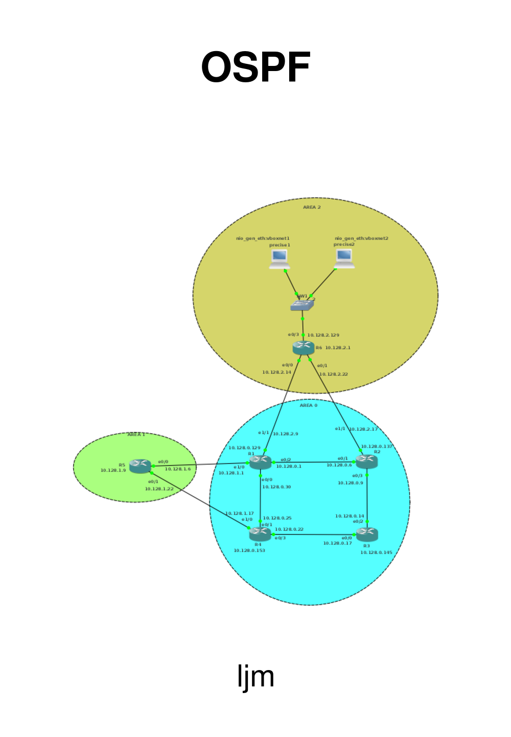
The network will look like this:

For R1, the basic setup is:
hostname R1
interface Loopback0
 ip address 10.128.0.129 255.255.255.248
!
interface Ethernet0/0
 ip address 10.128.0.30 255.255.255.248
 no shut
!
interface Ethernet0/2
 ip address 10.128.0.1 255.255.255.248
 no shut
!
For R2, the basic setup is:
hostname R2
interface Loopback0
 ip address 10.128.0.137 255.255.255.248
!
interface Ethernet0/1
 ip address 10.128.0.6 255.255.255.248
 no shut
!
interface Ethernet0/3
 ip address 10.128.0.9 255.255.255.248
 no shut
!
For R3, the basic setup is:
hostname R3
interface Loopback0
 ip address 10.128.0.145 255.255.255.248
!
interface Ethernet0/0
 ip address 10.128.0.17 255.255.255.248
 no shut
!
interface Ethernet0/2
 ip address 10.128.0.14 255.255.255.248
 no shut
!
For R4, the basic setup is:
hostname R4
interface Loopback0
 ip address 10.128.0.153 255.255.255.248
!
interface Ethernet0/1
 ip address 10.128.0.25 255.255.255.248
 no shut
!
interface Ethernet0/3
 ip address 10.128.0.22 255.255.255.248
 no shut
!
2.2. OSPF running
Enabling OSPF has the following steps:
-
enable
-
configure terminal
-
router ospf process-id
-
network ip-address wildcard-mask area area-id
-
end
The process-id is uniuqe per router and it allows you to run multiple
OSPF processes in 1 router. Why you would do that I do not understand,
especially not in a real production environment.
The IP-address/wildcard-mask are there to determine which interfaces
should participate in the OSPF routing. Cisco uses the wildcard-mask
to confuse people, because any sensible person would have used the
netmask.
Finaly, the aera-id is 0, because we're setting-up the backbone.
So, it will be:
router ospf 100
network 10.128.0.0 0.0.0.255 area 0
for all the routers in the backbone.
2.3. Verification
First verification is whether all the other addresses in area 0 are pingable.
Next step is to ask the routing table (here for R2):
R2#sh ip route
Codes: C - connected, S - static, R - RIP, M - mobile, B - BGP
       D - EIGRP, EX - EIGRP external, O - OSPF, IA - OSPF inter area
       N1 - OSPF NSSA external type 1, N2 - OSPF NSSA external type 2
       E1 - OSPF external type 1, E2 - OSPF external type 2
        i - IS-IS, su - IS-IS summary, L1 - IS-IS level-1, L2 - IS-IS level-2
       ia - IS-IS inter area, * - candidate default, U - per-user static route
          o - ODR, P - periodic downloaded static route
  Gateway of last resort is not set
       10.0.0.0/8 is variably subnetted, 8 subnets, 2 masks
   C       10.128.0.136/29 is directly connected, Loopback0
   O       10.128.0.129/32 [110/11] via 10.128.0.1, 00:02:00, Ethernet0/1
   O       10.128.0.153/32 [110/21] via 10.128.0.14, 00:02:00, Ethernet0/3
                           [110/21] via 10.128.0.1, 00:02:00, Ethernet0/1
   O       10.128.0.145/32 [110/11] via 10.128.0.14, 00:02:00, Ethernet0/3
   C       10.128.0.8/29 is directly connected, Ethernet0/3
   C       10.128.0.0/29 is directly connected, Ethernet0/1
   O       10.128.0.24/29 [110/20] via 10.128.0.1, 00:02:02, Ethernet0/1
   O       10.128.0.16/29 [110/20] via 10.128.0.14, 00:02:02, Ethernet0/3
   R2#
Luckily, Cisco tells us what the letters mean.
C
|
Directly connected. We see that the loopback address is directly connected and the two ethernet interfaces (e0/3 and e0/1) are directly connected. This is as expected.
|
O
|
A number of routes is learned through OSPF. The router knows about 10,128.0.16/29 through OSPF, and it knows it can reac that address using 10.128.0.14 as the gateway.
|
2.4. Packets
We'll be sniffing on R2 e0/3.
As expected, little traffic goes by in the normal situation. Just some
Hello Packets.

Some more packets arive when we remove a link (R1 to R2). It will not be
instatanous, but after a while:

Let's examine this update:
      LS Update Packet
        Number of LSAs: 1
           LSA-type 1 (Router-LSA), len 60
            .000 0000 0000 0001 = LS Age (seconds): 1
              0... .... .... .... = Do Not Age Flag: 0
              Options: 0x22 ((DC) Demand Circuits, (E) External Routing)
             LS Type: Router-LSA (1)
              Link State ID: 10.128.0.137
             Advertising Router: 10.128.0.137
              Sequence Number: 0x80000024
             Checksum: 0xb13e
This packet comes from the Link State ID 10.128.0.137, which is R2 (Cisco
chooses the IP address of the loopback as ID).
You see that this is an LSA-type 1. In this LSA you will find a list with all the directly
connected links of this router.
So, after R1 to R2 is gone, what does R2 advertise as being connected to?
-
Its loopback address 10.128.0.137; this is a stub
-
Its e0/1 10.128.0.6; this has become a stub when we removed the link to R1
-
The e0/3 network 10.128.0.8/29
And that is exactly what we see:
            Length: 60
               Flags: 0x00
               Number of Links: 3
              Type: Stub     ID: 10.128.0.137    Data: 255.255.255.255 Metric: 1
                 Link ID: 10.128.0.137 - IP network/subnet number
                Link Data: 255.255.255.255
                   Link Type: 3 - Connection to a stub network
                   Number of Metrics: 0 - TOS
                   0 Metric: 1
               Type: Transit  ID: 10.128.0.14     Data: 10.128.0.9      Metric: 10
                   Link ID: 10.128.0.14 - IP address of Designated Router
                   Link Data: 10.128.0.9
                   Link Type: 2 - Connection to a transit network
                   Number of Metrics: 0 - TOS
                   0 Metric: 10
               Type: Stub     ID: 10.128.0.0      Data: 255.255.255.248 Metric: 10
                   Link ID: 10.128.0.0 - IP network/subnet number
                   Link Data: 255.255.255.248
                   Link Type: 3 - Connection to a stub network
                   Number of Metrics: 0 - TOS
                   0 Metric: 10
Ah, but in fact, e0/1 should be a /32, because otherwise we would not be
able to reach R1 E0/2 10.128.0.1, you might say. Well, the resulting
routing table is:
R2>show ip route
Codes: C - connected, S - static, R - RIP, M - mobile, B - BGP
       D - EIGRP, EX - EIGRP external, O - OSPF, IA - OSPF inter area
          N1 - OSPF NSSA external type 1, N2 - OSPF NSSA external type 2
         E1 - OSPF external type 1, E2 - OSPF external type 2
        i - IS-IS, su - IS-IS summary, L1 - IS-IS level-1, L2 - IS-IS level-2
       ia - IS-IS inter area, * - candidate default, U - per-user static route
          o - ODR, P - periodic downloaded static route
  Gateway of last resort is not set
       10.0.0.0/8 is variably subnetted, 8 subnets, 2 masks
   C       10.128.0.136/29 is directly connected, Loopback0
   O       10.128.0.129/32 [110/31] via 10.128.0.14, 00:05:17, Ethernet0/3
   O       10.128.0.153/32 [110/21] via 10.128.0.14, 00:05:17, Ethernet0/3
   O       10.128.0.145/32 [110/11] via 10.128.0.14, 00:05:17, Ethernet0/3
   C       10.128.0.8/29 is directly connected, Ethernet0/3
   C       10.128.0.0/29 is directly connected, Ethernet0/1
   O       10.128.0.24/29 [110/30] via 10.128.0.14, 00:05:17, Ethernet0/3
   O       10.128.0.16/29 [110/20] via 10.128.0.14, 00:05:18, Ethernet0/3
So, no, it does not become a /32 and yes. the ping to 10.120.0.1 fails:
R2>ping 10.128.0.1
Type escape sequence to abort.
Sending 5, 100-byte ICMP Echos to 10.128.0.1, timeout is 2 seconds:
.....
Success rate is 0 percent (0/5)
R2>
Which is as expected.
3. Adding areas
We will now add some extra areas to our network.
Our first addition will be a simple router in area 1 with
a loopback address. The second will be a server network
with two servers on a switch and the third wil be a routed
client network, with multple routers in the area.
We'll use standard areas, and we'l not go into the
"a bit, but no too much"-stubby areas.
3.1. Area 1 - a simple router
First area is a simple router, which we wil divide in two
networks:
Network
|
Bits
|
Netmask
|
First
|
Last
|
Purpose
|
10.128.1.0
|
/29
|
255.255.255.248
|
10.128.1.1
|
10.128.1.6
|
Interconnection with the backbone
|
10.128.1.8
|
/29
|
255.255.255.248
|
10.128.1.9
|
10.128.1.14
|
Loopback of the router
|
The network will look like this:

We'll connect the router to e1/0 of R1 and on R1:
enable
config t
int e1/0
ip address 10.128.1.1 255.255.255.248
no shut
exit
And for R5, the area 1 router:
enable
config t
hostname R5
interface e0/0
ip address 10.128.1.6 255.255.255.248
no shut
interface Loopback0
ip address 10.128.1.9 255.255.255.248
exit
We will now be able to ping the R1 e1/0 interface from R5, but not much more. So the next step
is to get OSPF running. So, configure R1 for area 1:
router ospf 100
network 10.128.1.0 0.0.0.7 area 1
and R5:
router ospf 100
network 10.128.1.0 0.0.0.7 area 1
network 10.128.1.8 0.0.0.7 area 1
After some time, you will see a message from OSPF on the console:
*Mar 1 01:43:16.519: %OSPF-5-ADJCHG: Process 100, Nbr 10.128.0.129 on Ethernet0/0 from LOADING to FULL, Loading Done
And from that moment on, we can ping all the loopback adresses from anywhere.
On R5, our routing table looks like:
O IA    10.128.0.137/32 [110/21] via 10.128.1.1, 00:05:41, Ethernet0/0
O IA    10.128.0.129/32 [110/11] via 10.128.1.1, 00:05:41, Ethernet0/0
O IA    10.128.0.153/32 [110/21] via 10.128.1.1, 00:05:41, Ethernet0/0
O IA    10.128.0.145/32 [110/31] via 10.128.1.1, 00:05:41, Ethernet0/0
O IA    10.128.0.8/29 [110/30] via 10.128.1.1, 00:05:41, Ethernet0/0
C       10.128.1.8/29 is directly connected, Loopback0
O IA    10.128.0.0/29 [110/20] via 10.128.1.1, 00:05:43, Ethernet0/0
C       10.128.1.0/29 is directly connected, Ethernet0/0
O IA    10.128.0.24/29 [110/20] via 10.128.1.1, 00:05:43, Ethernet0/0
O IA    10.128.0.16/29 [110/30] via 10.128.1.1, 00:05:43, Ethernet0/0
The IA means that the routing is Inter Area.
So, let's connect R5 0 to R4 as well and see what that does.
Network
|
Bits
|
Netmask
|
First
|
Last
|
Purpose
|
10.128.1.16
|
/29
|
255.255.255.248
|
10.128.1.17
|
10.128.1.22
|
Interconnection R4 R5
|
But before we do the configuring, let's ask R3's routing table:
O       10.128.0.137/32 [110/11] via 10.128.0.9, 00:26:55, Ethernet0/2
O       10.128.0.129/32 [110/21] via 10.128.0.22, 00:26:55, Ethernet0/0
                        [110/21] via 10.128.0.9, 00:26:55, Ethernet0/2
O       10.128.0.153/32 [110/11] via 10.128.0.22, 00:26:55, Ethernet0/0
C       10.128.0.144/29 is directly connected, Loopback0
O IA    10.128.1.9/32 [110/31] via 10.128.0.22, 00:26:11, Ethernet0/0
                      [110/31] via 10.128.0.9, 00:26:11, Ethernet0/2
C       10.128.0.8/29 is directly connected, Ethernet0/2
O       10.128.0.0/29 [110/20] via 10.128.0.9, 00:26:56, Ethernet0/2
O IA    10.128.1.0/29 [110/30] via 10.128.0.22, 00:26:56, Ethernet0/0
                      [110/30] via 10.128.0.9, 00:26:56, Ethernet0/2
O       10.128.0.24/29 [110/20] via 10.128.0.22, 00:26:56, Ethernet0/0
C       10.128.0.16/29 is directly connected, Ethernet0/0
For R4:
enable
config t
int e1/0
ip address 10.128.1.17 255.255.255.248
no shut
router ospf 100
network 10.128.1.16 0.0.0.7 area 1
exit
and for R5:
enable
config t
int e0/1
ip address 10.128.1.22 255.255.255.248
no shut
router ospf 100
network 10.128.1.16 0.0.0.7 area 1
exit
And, after the OSPF messages, ask the routing table for R3 again:
O       10.128.0.137/32 [110/11] via 10.128.0.9, 00:00:21, Ethernet0/2
O       10.128.0.129/32 [110/21] via 10.128.0.22, 00:00:21, Ethernet0/0
                        [110/21] via 10.128.0.9, 00:00:21, Ethernet0/2
O       10.128.0.153/32 [110/11] via 10.128.0.22, 00:00:21, Ethernet0/0
C       10.128.0.144/29 is directly connected, Loopback0
O IA    10.128.1.9/32 [110/21] via 10.128.0.22, 00:00:12, Ethernet0/0
C       10.128.0.8/29 is directly connected, Ethernet0/2
O       10.128.0.0/29 [110/20] via 10.128.0.9, 00:00:22, Ethernet0/2
O IA    10.128.1.0/29 [110/30] via 10.128.0.22, 00:00:13, Ethernet0/0
                      [110/30] via 10.128.0.9, 00:00:13, Ethernet0/2
O       10.128.0.24/29 [110/20] via 10.128.0.22, 00:00:22, Ethernet0/0
C       10.128.0.16/29 is directly connected, Ethernet0/0
O IA    10.128.1.16/29 [110/20] via 10.128.0.22, 00:00:24, Ethernet0/0
You can see the difference:
< O IA    10.128.1.9/32 [110/31] via 10.128.0.22
<                       [110/31] via 10.128.0.9
---
> O IA    10.128.1.9/32 [110/21] via 10.128.0.22
> O IA    10.128.1.16/29 [110/20] via 10.128.0.22
The route from R3 to R5's loopback via R2 is now gone. because the route
via R4 is now shorter. And of course, the interconnection between R4 and
R5 is added.
3.2. Area 2: a number of hosts
Next, we'll add a switched network with hosts in it. Area 2 will be
10.128.2.0/24, with the interconnection networks in the lower half
and the server network in the upper /25.
Network
|
Bits
|
Netmask
|
First
|
Last
|
Purpose
|
10.128.2.0
|
/29
|
255.255.255.248
|
10.128.2.1
|
10.128.2.6
|
Loopback of the router
|
10.128.2.8
|
/29
|
255.255.255.248
|
10.128.2.9
|
10.128.2.14
|
Interconnection with R1
|
10.128.2.16
|
/29
|
255.255.255.248
|
10.128.2.17
|
10.128.2.22
|
Interconnection with R2
|
10.128.2.128
|
/25
|
255.255.255.128
|
10.128.2.129
|
10.128.2.254
|
Serverfarm
|
That will make R6 as configuration:
enable
config t
hostname R6
interface Loopback0
ip address 10.128.2.1 255.255.255.248
int e0/0
ip address 10.128.2.14 255.255.255.248
no shut
int e0/1
ip address 10.128.2.22 255.255.255.248
no shut
int e0/3
ip address 10.128.2.129 255.255.255.128
no shut
router ospf 100
network 10.128.2.0 0.0.0.255 area 2
exit
For R1, we'll add:
interface e1/1
ip address 10.128.2.9 255.255.255.248
no shut
router ospf 100
network 10.128.2.8 0.0.0.7 area 2
and for R2:
int e1/1
ip address 10.128.2.17 255.255.255.248
no shut
router ospf 100
network 10.128.2.16 0.0.0.7 area 2
And after OSPF is converged, we're able to ping R6's loopback from R5.
Then we'll add some hosts to the area. Our Vagrant file looks like this:
# -*- mode: ruby -*-
# vi: set ft=ruby :
# Vagrantfile API/syntax version. Don't touch unless you know what you're doing!
VAGRANTFILE_API_VERSION = "2"
Vagrant.configure(VAGRANTFILE_API_VERSION) do |config|
	config.vm.define :precise1 do |t|
		t.vm.box = "hashicorp/precise64"
		t.vm.box_url = "file:////links/virt_comp/vagrant/boxes/precise64.box"
		t.vm.provider "virtualbox" do |prov|
			prov.customize ["modifyvm", :id, "--nic2", "hostonly", "--hostonlyadapter2", "vboxnet1" ]
		end
		t.vm.provision "shell", path: "./setup.precise1.sh"
	end
	config.vm.define :precise2 do |t|
		t.vm.box = "hashicorp/precise64"
		t.vm.box_url = "file:////links/virt_comp/vagrant/boxes/precise64.box"
		t.vm.provider "virtualbox" do |prov|
			prov.customize ["modifyvm", :id, "--nic2", "hostonly", "--hostonlyadapter2", "vboxnet1" ]
		end
		t.vm.provision "shell", path: "./setup.precise2.sh"
	end
end
You see that both machines are connected to vboxnet1. I could have used a switch from gns3, but this works
better. The set-up for the macines looks like this:
#!/bin/bash
ifconfig eth1  10.128.2.151 netmask 255.255.255.128 up
route add -net 10.128.0.0 netmask 255.255.0.0 gw 10.128.2.129
apt-get -y  update
apt-get -y  install apache2
cat > /var/www/index.html <<EOF
<html>
  <body>
    <h1>Precise1</h1>
</body>
</html>
EOF
What you see is the definition of the network and the installation of a
webserver. Finally, you will see a default web-page that identifies the
machine.
After a
vagrant up
we can ping our area 1 router's loopback from precise1:
vagrant ssh precise1 -- ping -c2 10.128.1.9
PING 10.128.1.9 (10.128.1.9) 56(84) bytes of data.
64 bytes from 10.128.1.9: icmp_req=1 ttl=253 time=42.2 ms
64 bytes from 10.128.1.9: icmp_req=2 ttl=253 time=32.0 ms
--- 10.128.1.9 ping statistics ---
2 packets transmitted, 2 received, 0% packet loss, time 1000ms
rtt min/avg/max/mdev = 32.019/37.114/42.209/5.095 ms
Which proves that routing works.
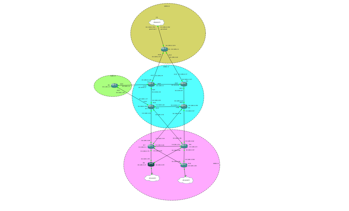
3.3. Area 3: complicated
For Area 3 we'll make a more complicated area. First the network-calculations:
Network
|
Bits
|
Netmask
|
First
|
Last
|
Purpose
|
10.128.3.0
|
/29
|
255.255.255.248
|
10.128.3.1
|
10.128.3.6
|
Loopback R7
|
10.128.3.8
|
/29
|
255.255.255.248
|
10.128.3.9
|
10.128.3.14
|
Loopback R8
|
10.128.3.16
|
/29
|
255.255.255.248
|
10.128.3.17
|
10.128.3.22
|
Loopback R9
|
10.128.3.24
|
/29
|
255.255.255.248
|
10.128.3.25
|
10.128.3.30
|
Loopback R10
|
10.128.3.32
|
/29
|
255.255.255.248
|
10.128.3.33
|
10.128.3.38
|
R4 to R7
|
10.128.3.40
|
/29
|
255.255.255.248
|
10.128.3.41
|
10.128.3.46
|
R4 to R8
|
10.128.3.48
|
/29
|
255.255.255.248
|
10.128.3.49
|
10.128.3.54
|
R3 to R7
|
10.128.3.56
|
/29
|
255.255.255.248
|
10.128.3.57
|
10.128.3.62
|
R3 to R8
|
10.128.3.64
|
/29
|
255.255.255.248
|
10.128.3.65
|
10.128.3.70
|
R7 to R8
|
10.128.3.72
|
/29
|
255.255.255.248
|
10.128.3.73
|
10.128.3.78
|
R7 to R9
|
10.128.3.80
|
/29
|
255.255.255.248
|
10.128.3.81
|
10.128.3.86
|
R7 to R10
|
10.128.3.88
|
/29
|
255.255.255.248
|
10.128.3.89
|
10.128.3.94
|
R8 to R9
|
10.128.3.96
|
/29
|
255.255.255.248
|
10.128.3.97
|
10.128.3.102
|
R8 to R10
|
10.128.3.104
|
/29
|
255.255.255.248
|
10.128.3.105
|
10.128.3.110
|
Client area R9
|
10.128.3.112
|
/29
|
255.255.255.248
|
10.128.3.113
|
10.128.3.118
|
Client area R9
|
10.128.3.120
|
/29
|
255.255.255.248
|
10.128.3.121
|
10.128.3.126
|
Client area R10
|
10.128.3.128
|
/29
|
255.255.255.248
|
10.128.3.129
|
10.128.3.134
|
Client area R10
|
For the different routers, we'll need to add some configurations.
R4:
int e1/1
ip address 10.128.3.33 255.255.255.248
no shut
int e1/2
ip address 10.128.3.41 255.255.255.248
no shut
router ospf 100
network 10.128.3.32 0.0.0.7 area 3
network 10.128.3.40 0.0.0.7 area 3
R3:
int e1/1
ip address 10.128.3.57 255.255.255.248
no shut
int e1/2
ip address 10.128.3.49 255.255.255.248
no shut
router ospf 100
network 10.128.3.48 0.0.0.7 area 3
network 10.128.3.56 0.0.0.7 area 3
The area 3 routers will get their full configuration.
R7:
enable
config t
hostname R7
int loopback 0
ip address 10.128.3.1  255.255.255.248
int e0/0
ip address 10.128.3.38  255.255.255.248
no shut
int e0/1
ip address 10.128.3.54  255.255.255.248
no shut
int e0/3
ip address 10.128.3.65  255.255.255.248
no shut
int e1/0
ip address 10.128.3.73  255.255.255.248
no shut
int e1/1
ip address 10.128.3.81  255.255.255.248
no shut
router ospf 100
network 10.128.3.0 0.0.0.7 area 3
network 10.128.3.32 0.0.0.7 area 3
network 10.128.3.48 0.0.0.7 area 3
network 10.128.3.64 0.0.0.7 area 3
network 10.128.3.72 0.0.0.7 area 3
network 10.128.3.80 0.0.0.7 area 3
exit
R8:
enable
config t
hostname R8
int loopback 0
ip address 10.128.3.9  255.255.255.248
int e0/0
ip address 10.128.3.62  255.255.255.248
no shut
int e0/1
ip address 10.128.3.46  255.255.255.248
no shut
int e0/3
ip address 10.128.3.70  255.255.255.248
no shut
int e1/0
ip address 10.128.3.89  255.255.255.248
no shut
int e1/1
ip address 10.128.3.97  255.255.255.248
no shut
router ospf 100
network 10.128.3.0 0.0.0.255 area 3
exit
A different approach towards the specification of the network in R7 and R8 is given.
For R7, only the networks on the interfaces are specified, for R8, the complete area
is specified.
R8's configuration is potentially easier in large networks, because it saves us the
trouble of keeping long lists of networks.
R9:
enable
config t
hostname R9
int loopback 0
ip address 10.128.3.17  255.255.255.248
int e0/0
ip address 10.128.3.78  255.255.255.248
no shut
int e0/1
ip address 10.128.3.94  255.255.255.248
no shut
router ospf 100
network 10.128.3.0 0.0.0.255 area 3
exit
R10:
enable
config t
hostname R10
int loopback 0
ip address 10.128.3.25  255.255.255.248
int e0/0
ip address 10.128.3.86  255.255.255.248
no shut
int e0/1
ip address 10.128.3.102  255.255.255.248
no shut
router ospf 100
network 10.128.3.0 0.0.0.255 area 3
exit
And after that we can ping our servers from R10:
R10#ping 10.128.2.151
Type escape sequence to abort.
Sending 5, 100-byte ICMP Echos to 10.128.2.151, timeout is 2 seconds:
!!!!!
Success rate is 100 percent (5/5), round-trip min/avg/max = 56/79/104 ms
We had also defined some client networks, which we have not yet configured.
First, we'll add two clients to our Vagrantfile:
# -*- mode: ruby -*-
# vi: set ft=ruby :
# Vagrantfile API/syntax version. Don't touch unless you know what you're doing!
VAGRANTFILE_API_VERSION = "2"
Vagrant.configure(VAGRANTFILE_API_VERSION) do |config|
	config.vm.define :precise1 do |t|
		t.vm.box = "hashicorp/precise64"
		t.vm.box_url = "file:////links/virt_comp/vagrant/boxes/precise64.box"
		t.vm.provider "virtualbox" do |prov|
			prov.customize ["modifyvm", :id, "--nic2", "hostonly", "--hostonlyadapter2", "vboxnet1" ]
		end
		t.vm.provision "shell", path: "./setup.precise1.sh"
	end
	config.vm.define :precise2 do |t|
		t.vm.box = "hashicorp/precise64"
		t.vm.box_url = "file:////links/virt_comp/vagrant/boxes/precise64.box"
		t.vm.provider "virtualbox" do |prov|
			prov.customize ["modifyvm", :id, "--nic2", "hostonly", "--hostonlyadapter2", "vboxnet1" ]
		end
		t.vm.provision "shell", path: "./setup.precise2.sh"
	end
	config.vm.define :precise3 do |t|
		t.vm.box = "hashicorp/precise64"
		t.vm.box_url = "file:////links/virt_comp/vagrant/boxes/precise64.box"
		t.vm.provider "virtualbox" do |prov|
			prov.customize ["modifyvm", :id, "--nic2", "hostonly", "--hostonlyadapter2", "vboxnet3" ]
		end
		t.vm.provision "shell", path: "./setup.precise3.sh"
	end
	config.vm.define :precise4 do |t|
		t.vm.box = "hashicorp/precise64"
		t.vm.box_url = "file:////links/virt_comp/vagrant/boxes/precise64.box"
		t.vm.provider "virtualbox" do |prov|
			prov.customize ["modifyvm", :id, "--nic2", "hostonly", "--hostonlyadapter2", "vboxnet4" ]
		end
		t.vm.provision "shell", path: "./setup.precise4.sh"
	end
end
And create the appropriate start-up scripts:
#!/bin/bash
#precise3
ifconfig eth1  10.128.3.110 netmask 255.255.255.248 up
route add -net 10.128.0.0 netmask 255.255.0.0 gw 10.128.3.105
#!/bin/bash
# precise4
ifconfig eth1  10.128.3.126 netmask 255.255.255.248 up
route add -net 10.128.0.0 netmask 255.255.0.0 gw 10.128.3.121
After a
vagrant up
we'll connect precise3 and precise4 to e0/0 of R9 and R10 respectively.
For R9:
int e1/0
ip address 10.128.3.105 255.255.255.248
no shut
and for R10:
int e1/0
ip address 10.128.3.121 255.255.255.248
no shut
And from our client, we can ping our serve: