3. Adding areas
We will now add some extra areas to our network.
Our first addition will be a simple router in area 1 with
a loopback address. The second will be a server network
with two servers on a switch and the third wil be a routed
client network, with multple routers in the area.
We'll use standard areas, and we'l not go into the
"a bit, but no too much"-stubby areas.
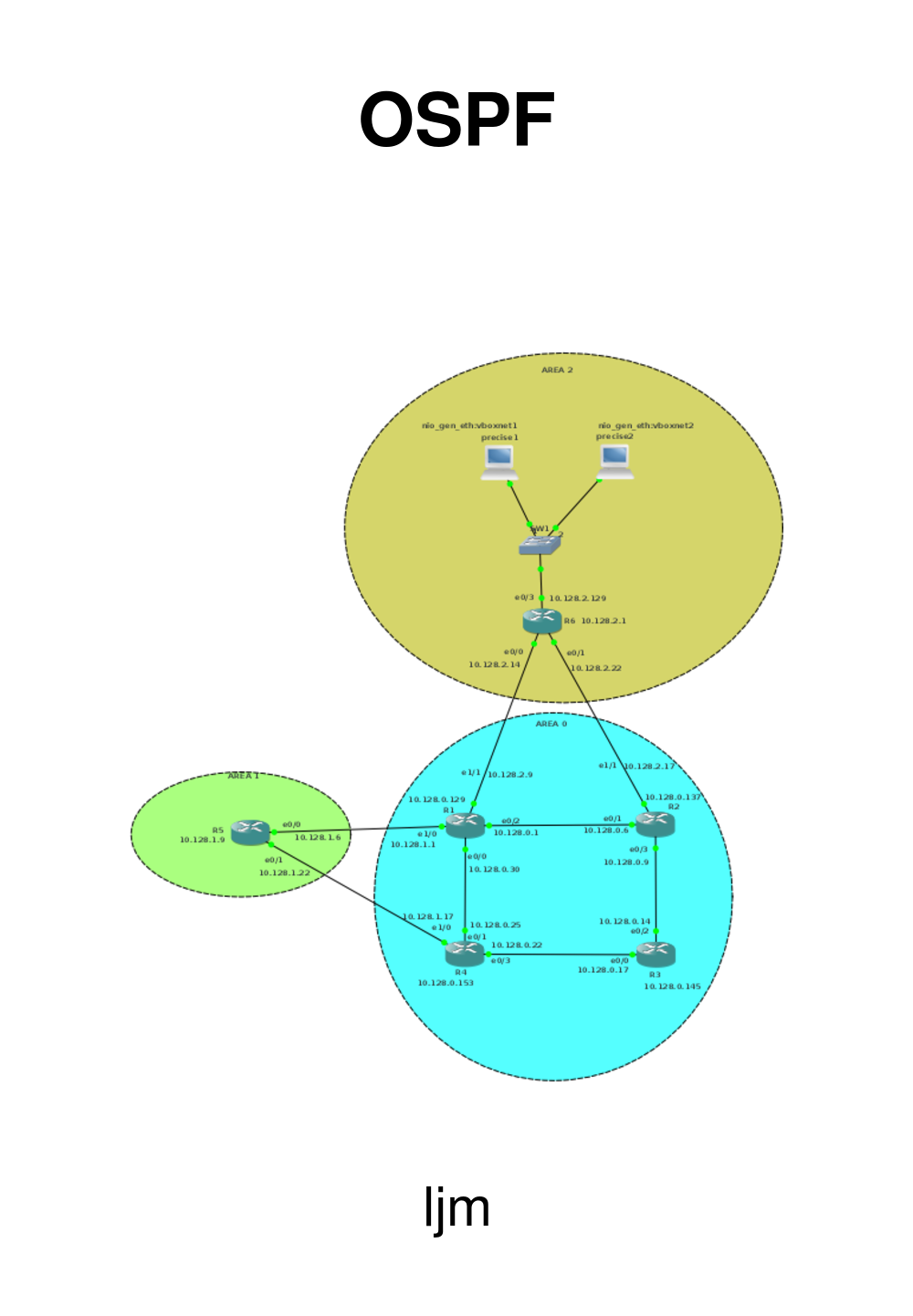
3.1. Area 1 - a simple router
First area is a simple router, which we wil divide in two
networks:
Network
|
Bits
|
Netmask
|
First
|
Last
|
Purpose
|
10.128.1.0
|
/29
|
255.255.255.248
|
10.128.1.1
|
10.128.1.6
|
Interconnection with the backbone
|
10.128.1.8
|
/29
|
255.255.255.248
|
10.128.1.9
|
10.128.1.14
|
Loopback of the router
|
The network will look like this:

We'll connect the router to e1/0 of R1 and on R1:
enable
config t
int e1/0
ip address 10.128.1.1 255.255.255.248
no shut
exit
And for R5, the area 1 router:
enable
config t
hostname R5
interface e0/0
ip address 10.128.1.6 255.255.255.248
no shut
interface Loopback0
ip address 10.128.1.9 255.255.255.248
exit
We will now be able to ping the R1 e1/0 interface from R5, but not much more. So the next step
is to get OSPF running. So, configure R1 for area 1:
router ospf 100
network 10.128.1.0 0.0.0.7 area 1
and R5:
router ospf 100
network 10.128.1.0 0.0.0.7 area 1
network 10.128.1.8 0.0.0.7 area 1
After some time, you will see a message from OSPF on the console:
*Mar 1 01:43:16.519: %OSPF-5-ADJCHG: Process 100, Nbr 10.128.0.129 on Ethernet0/0 from LOADING to FULL, Loading Done
And from that moment on, we can ping all the loopback adresses from anywhere.
On R5, our routing table looks like:
O IA    10.128.0.137/32 [110/21] via 10.128.1.1, 00:05:41, Ethernet0/0
O IA    10.128.0.129/32 [110/11] via 10.128.1.1, 00:05:41, Ethernet0/0
O IA    10.128.0.153/32 [110/21] via 10.128.1.1, 00:05:41, Ethernet0/0
O IA    10.128.0.145/32 [110/31] via 10.128.1.1, 00:05:41, Ethernet0/0
O IA    10.128.0.8/29 [110/30] via 10.128.1.1, 00:05:41, Ethernet0/0
C       10.128.1.8/29 is directly connected, Loopback0
O IA    10.128.0.0/29 [110/20] via 10.128.1.1, 00:05:43, Ethernet0/0
C       10.128.1.0/29 is directly connected, Ethernet0/0
O IA    10.128.0.24/29 [110/20] via 10.128.1.1, 00:05:43, Ethernet0/0
O IA    10.128.0.16/29 [110/30] via 10.128.1.1, 00:05:43, Ethernet0/0
The IA means that the routing is Inter Area.
So, let's connect R5 0 to R4 as well and see what that does.
Network
|
Bits
|
Netmask
|
First
|
Last
|
Purpose
|
10.128.1.16
|
/29
|
255.255.255.248
|
10.128.1.17
|
10.128.1.22
|
Interconnection R4 R5
|
But before we do the configuring, let's ask R3's routing table:
O       10.128.0.137/32 [110/11] via 10.128.0.9, 00:26:55, Ethernet0/2
O       10.128.0.129/32 [110/21] via 10.128.0.22, 00:26:55, Ethernet0/0
                        [110/21] via 10.128.0.9, 00:26:55, Ethernet0/2
O       10.128.0.153/32 [110/11] via 10.128.0.22, 00:26:55, Ethernet0/0
C       10.128.0.144/29 is directly connected, Loopback0
O IA    10.128.1.9/32 [110/31] via 10.128.0.22, 00:26:11, Ethernet0/0
                      [110/31] via 10.128.0.9, 00:26:11, Ethernet0/2
C       10.128.0.8/29 is directly connected, Ethernet0/2
O       10.128.0.0/29 [110/20] via 10.128.0.9, 00:26:56, Ethernet0/2
O IA    10.128.1.0/29 [110/30] via 10.128.0.22, 00:26:56, Ethernet0/0
                      [110/30] via 10.128.0.9, 00:26:56, Ethernet0/2
O       10.128.0.24/29 [110/20] via 10.128.0.22, 00:26:56, Ethernet0/0
C       10.128.0.16/29 is directly connected, Ethernet0/0
For R4:
enable
config t
int e1/0
ip address 10.128.1.17 255.255.255.248
no shut
router ospf 100
network 10.128.1.16 0.0.0.7 area 1
exit
and for R5:
enable
config t
int e0/1
ip address 10.128.1.22 255.255.255.248
no shut
router ospf 100
network 10.128.1.16 0.0.0.7 area 1
exit
And, after the OSPF messages, ask the routing table for R3 again:
O       10.128.0.137/32 [110/11] via 10.128.0.9, 00:00:21, Ethernet0/2
O       10.128.0.129/32 [110/21] via 10.128.0.22, 00:00:21, Ethernet0/0
                        [110/21] via 10.128.0.9, 00:00:21, Ethernet0/2
O       10.128.0.153/32 [110/11] via 10.128.0.22, 00:00:21, Ethernet0/0
C       10.128.0.144/29 is directly connected, Loopback0
O IA    10.128.1.9/32 [110/21] via 10.128.0.22, 00:00:12, Ethernet0/0
C       10.128.0.8/29 is directly connected, Ethernet0/2
O       10.128.0.0/29 [110/20] via 10.128.0.9, 00:00:22, Ethernet0/2
O IA    10.128.1.0/29 [110/30] via 10.128.0.22, 00:00:13, Ethernet0/0
                      [110/30] via 10.128.0.9, 00:00:13, Ethernet0/2
O       10.128.0.24/29 [110/20] via 10.128.0.22, 00:00:22, Ethernet0/0
C       10.128.0.16/29 is directly connected, Ethernet0/0
O IA    10.128.1.16/29 [110/20] via 10.128.0.22, 00:00:24, Ethernet0/0
You can see the difference:
< O IA    10.128.1.9/32 [110/31] via 10.128.0.22
<                       [110/31] via 10.128.0.9
---
> O IA    10.128.1.9/32 [110/21] via 10.128.0.22
> O IA    10.128.1.16/29 [110/20] via 10.128.0.22
The route from R3 to R5's loopback via R2 is now gone. because the route
via R4 is now shorter. And of course, the interconnection between R4 and
R5 is added.
3.2. Area 2: a number of hosts
Next, we'll add a switched network with hosts in it. Area 2 will be
10.128.2.0/24, with the interconnection networks in the lower half
and the server network in the upper /25.
Network
|
Bits
|
Netmask
|
First
|
Last
|
Purpose
|
10.128.2.0
|
/29
|
255.255.255.248
|
10.128.2.1
|
10.128.2.6
|
Loopback of the router
|
10.128.2.8
|
/29
|
255.255.255.248
|
10.128.2.9
|
10.128.2.14
|
Interconnection with R1
|
10.128.2.16
|
/29
|
255.255.255.248
|
10.128.2.17
|
10.128.2.22
|
Interconnection with R2
|
10.128.2.128
|
/25
|
255.255.255.128
|
10.128.2.129
|
10.128.2.254
|
Serverfarm
|
That will make R6 as configuration:
enable
config t
hostname R6
interface Loopback0
ip address 10.128.2.1 255.255.255.248
int e0/0
ip address 10.128.2.14 255.255.255.248
no shut
int e0/1
ip address 10.128.2.22 255.255.255.248
no shut
int e0/3
ip address 10.128.2.129 255.255.255.128
no shut
router ospf 100
network 10.128.2.0 0.0.0.255 area 2
exit
For R1, we'll add:
interface e1/1
ip address 10.128.2.9 255.255.255.248
no shut
router ospf 100
network 10.128.2.8 0.0.0.7 area 2
and for R2:
int e1/1
ip address 10.128.2.17 255.255.255.248
no shut
router ospf 100
network 10.128.2.16 0.0.0.7 area 2
And after OSPF is converged, we're able to ping R6's loopback from R5.
Then we'll add some hosts to the area. Our Vagrant file looks like this:
# -*- mode: ruby -*-
# vi: set ft=ruby :
# Vagrantfile API/syntax version. Don't touch unless you know what you're doing!
VAGRANTFILE_API_VERSION = "2"
Vagrant.configure(VAGRANTFILE_API_VERSION) do |config|
	config.vm.define :precise1 do |t|
		t.vm.box = "hashicorp/precise64"
		t.vm.box_url = "file:////links/virt_comp/vagrant/boxes/precise64.box"
		t.vm.provider "virtualbox" do |prov|
			prov.customize ["modifyvm", :id, "--nic2", "hostonly", "--hostonlyadapter2", "vboxnet1" ]
		end
		t.vm.provision "shell", path: "./setup.precise1.sh"
	end
	config.vm.define :precise2 do |t|
		t.vm.box = "hashicorp/precise64"
		t.vm.box_url = "file:////links/virt_comp/vagrant/boxes/precise64.box"
		t.vm.provider "virtualbox" do |prov|
			prov.customize ["modifyvm", :id, "--nic2", "hostonly", "--hostonlyadapter2", "vboxnet1" ]
		end
		t.vm.provision "shell", path: "./setup.precise2.sh"
	end
end
You see that both machines are connected to vboxnet1. I could have used a switch from gns3, but this works
better. The set-up for the macines looks like this:
#!/bin/bash
ifconfig eth1  10.128.2.151 netmask 255.255.255.128 up
route add -net 10.128.0.0 netmask 255.255.0.0 gw 10.128.2.129
apt-get -y  update
apt-get -y  install apache2
cat > /var/www/index.html <<EOF
<html>
  <body>
    <h1>Precise1</h1>
</body>
</html>
EOF
What you see is the definition of the network and the installation of a
webserver. Finally, you will see a default web-page that identifies the
machine.
After a
vagrant up
we can ping our area 1 router's loopback from precise1:
vagrant ssh precise1 -- ping -c2 10.128.1.9
PING 10.128.1.9 (10.128.1.9) 56(84) bytes of data.
64 bytes from 10.128.1.9: icmp_req=1 ttl=253 time=42.2 ms
64 bytes from 10.128.1.9: icmp_req=2 ttl=253 time=32.0 ms
--- 10.128.1.9 ping statistics ---
2 packets transmitted, 2 received, 0% packet loss, time 1000ms
rtt min/avg/max/mdev = 32.019/37.114/42.209/5.095 ms
Which proves that routing works.
3.3. Area 3: complicated
For Area 3 we'll make a more complicated area. First the network-calculations:
Network
|
Bits
|
Netmask
|
First
|
Last
|
Purpose
|
10.128.3.0
|
/29
|
255.255.255.248
|
10.128.3.1
|
10.128.3.6
|
Loopback R7
|
10.128.3.8
|
/29
|
255.255.255.248
|
10.128.3.9
|
10.128.3.14
|
Loopback R8
|
10.128.3.16
|
/29
|
255.255.255.248
|
10.128.3.17
|
10.128.3.22
|
Loopback R9
|
10.128.3.24
|
/29
|
255.255.255.248
|
10.128.3.25
|
10.128.3.30
|
Loopback R10
|
10.128.3.32
|
/29
|
255.255.255.248
|
10.128.3.33
|
10.128.3.38
|
R4 to R7
|
10.128.3.40
|
/29
|
255.255.255.248
|
10.128.3.41
|
10.128.3.46
|
R4 to R8
|
10.128.3.48
|
/29
|
255.255.255.248
|
10.128.3.49
|
10.128.3.54
|
R3 to R7
|
10.128.3.56
|
/29
|
255.255.255.248
|
10.128.3.57
|
10.128.3.62
|
R3 to R8
|
10.128.3.64
|
/29
|
255.255.255.248
|
10.128.3.65
|
10.128.3.70
|
R7 to R8
|
10.128.3.72
|
/29
|
255.255.255.248
|
10.128.3.73
|
10.128.3.78
|
R7 to R9
|
10.128.3.80
|
/29
|
255.255.255.248
|
10.128.3.81
|
10.128.3.86
|
R7 to R10
|
10.128.3.88
|
/29
|
255.255.255.248
|
10.128.3.89
|
10.128.3.94
|
R8 to R9
|
10.128.3.96
|
/29
|
255.255.255.248
|
10.128.3.97
|
10.128.3.102
|
R8 to R10
|
10.128.3.104
|
/29
|
255.255.255.248
|
10.128.3.105
|
10.128.3.110
|
Client area R9
|
10.128.3.112
|
/29
|
255.255.255.248
|
10.128.3.113
|
10.128.3.118
|
Client area R9
|
10.128.3.120
|
/29
|
255.255.255.248
|
10.128.3.121
|
10.128.3.126
|
Client area R10
|
10.128.3.128
|
/29
|
255.255.255.248
|
10.128.3.129
|
10.128.3.134
|
Client area R10
|
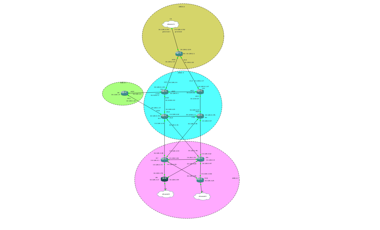
For the different routers, we'll need to add some configurations.
R4:
int e1/1
ip address 10.128.3.33 255.255.255.248
no shut
int e1/2
ip address 10.128.3.41 255.255.255.248
no shut
router ospf 100
network 10.128.3.32 0.0.0.7 area 3
network 10.128.3.40 0.0.0.7 area 3
R3:
int e1/1
ip address 10.128.3.57 255.255.255.248
no shut
int e1/2
ip address 10.128.3.49 255.255.255.248
no shut
router ospf 100
network 10.128.3.48 0.0.0.7 area 3
network 10.128.3.56 0.0.0.7 area 3
The area 3 routers will get their full configuration.
R7:
enable
config t
hostname R7
int loopback 0
ip address 10.128.3.1  255.255.255.248
int e0/0
ip address 10.128.3.38  255.255.255.248
no shut
int e0/1
ip address 10.128.3.54  255.255.255.248
no shut
int e0/3
ip address 10.128.3.65  255.255.255.248
no shut
int e1/0
ip address 10.128.3.73  255.255.255.248
no shut
int e1/1
ip address 10.128.3.81  255.255.255.248
no shut
router ospf 100
network 10.128.3.0 0.0.0.7 area 3
network 10.128.3.32 0.0.0.7 area 3
network 10.128.3.48 0.0.0.7 area 3
network 10.128.3.64 0.0.0.7 area 3
network 10.128.3.72 0.0.0.7 area 3
network 10.128.3.80 0.0.0.7 area 3
exit
R8:
enable
config t
hostname R8
int loopback 0
ip address 10.128.3.9  255.255.255.248
int e0/0
ip address 10.128.3.62  255.255.255.248
no shut
int e0/1
ip address 10.128.3.46  255.255.255.248
no shut
int e0/3
ip address 10.128.3.70  255.255.255.248
no shut
int e1/0
ip address 10.128.3.89  255.255.255.248
no shut
int e1/1
ip address 10.128.3.97  255.255.255.248
no shut
router ospf 100
network 10.128.3.0 0.0.0.255 area 3
exit
A different approach towards the specification of the network in R7 and R8 is given.
For R7, only the networks on the interfaces are specified, for R8, the complete area
is specified.
R8's configuration is potentially easier in large networks, because it saves us the
trouble of keeping long lists of networks.
R9:
enable
config t
hostname R9
int loopback 0
ip address 10.128.3.17  255.255.255.248
int e0/0
ip address 10.128.3.78  255.255.255.248
no shut
int e0/1
ip address 10.128.3.94  255.255.255.248
no shut
router ospf 100
network 10.128.3.0 0.0.0.255 area 3
exit
R10:
enable
config t
hostname R10
int loopback 0
ip address 10.128.3.25  255.255.255.248
int e0/0
ip address 10.128.3.86  255.255.255.248
no shut
int e0/1
ip address 10.128.3.102  255.255.255.248
no shut
router ospf 100
network 10.128.3.0 0.0.0.255 area 3
exit
And after that we can ping our servers from R10:
R10#ping 10.128.2.151
Type escape sequence to abort.
Sending 5, 100-byte ICMP Echos to 10.128.2.151, timeout is 2 seconds:
!!!!!
Success rate is 100 percent (5/5), round-trip min/avg/max = 56/79/104 ms
We had also defined some client networks, which we have not yet configured.
First, we'll add two clients to our Vagrantfile:
# -*- mode: ruby -*-
# vi: set ft=ruby :
# Vagrantfile API/syntax version. Don't touch unless you know what you're doing!
VAGRANTFILE_API_VERSION = "2"
Vagrant.configure(VAGRANTFILE_API_VERSION) do |config|
	config.vm.define :precise1 do |t|
		t.vm.box = "hashicorp/precise64"
		t.vm.box_url = "file:////links/virt_comp/vagrant/boxes/precise64.box"
		t.vm.provider "virtualbox" do |prov|
			prov.customize ["modifyvm", :id, "--nic2", "hostonly", "--hostonlyadapter2", "vboxnet1" ]
		end
		t.vm.provision "shell", path: "./setup.precise1.sh"
	end
	config.vm.define :precise2 do |t|
		t.vm.box = "hashicorp/precise64"
		t.vm.box_url = "file:////links/virt_comp/vagrant/boxes/precise64.box"
		t.vm.provider "virtualbox" do |prov|
			prov.customize ["modifyvm", :id, "--nic2", "hostonly", "--hostonlyadapter2", "vboxnet1" ]
		end
		t.vm.provision "shell", path: "./setup.precise2.sh"
	end
	config.vm.define :precise3 do |t|
		t.vm.box = "hashicorp/precise64"
		t.vm.box_url = "file:////links/virt_comp/vagrant/boxes/precise64.box"
		t.vm.provider "virtualbox" do |prov|
			prov.customize ["modifyvm", :id, "--nic2", "hostonly", "--hostonlyadapter2", "vboxnet3" ]
		end
		t.vm.provision "shell", path: "./setup.precise3.sh"
	end
	config.vm.define :precise4 do |t|
		t.vm.box = "hashicorp/precise64"
		t.vm.box_url = "file:////links/virt_comp/vagrant/boxes/precise64.box"
		t.vm.provider "virtualbox" do |prov|
			prov.customize ["modifyvm", :id, "--nic2", "hostonly", "--hostonlyadapter2", "vboxnet4" ]
		end
		t.vm.provision "shell", path: "./setup.precise4.sh"
	end
end
And create the appropriate start-up scripts:
#!/bin/bash
#precise3
ifconfig eth1  10.128.3.110 netmask 255.255.255.248 up
route add -net 10.128.0.0 netmask 255.255.0.0 gw 10.128.3.105
#!/bin/bash
# precise4
ifconfig eth1  10.128.3.126 netmask 255.255.255.248 up
route add -net 10.128.0.0 netmask 255.255.0.0 gw 10.128.3.121
After a
vagrant up
we'll connect precise3 and precise4 to e0/0 of R9 and R10 respectively.
For R9:
int e1/0
ip address 10.128.3.105 255.255.255.248
no shut
and for R10:
int e1/0
ip address 10.128.3.121 255.255.255.248
no shut
And from our client, we can ping our serve: