1. OSPF intro
1.1. Unlike RIP
While RIP is easy enough to implement and use in small networks, it becomes a
problem if the network becomes larger.
The solution is the use of another protocol: OSPF
OSPF uses a different protocol than RIP, and to understand OSPF, a set
of concepts must be clear.
1.2. Link State and Distance Vector
For routing, there are two types of protocols:
-
Distance Vector
-
Link State
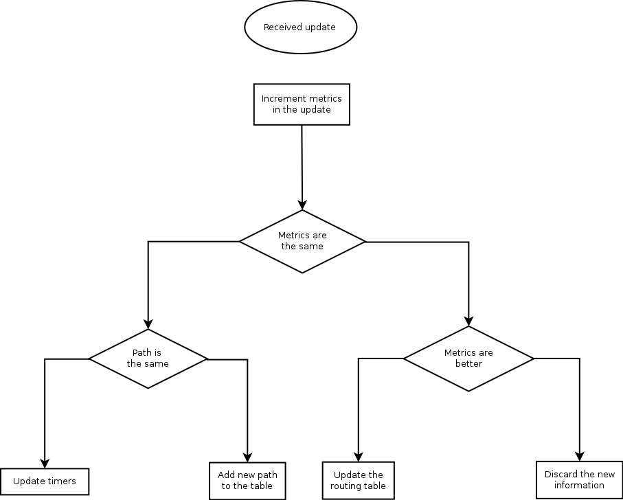
Distance vector protocols, like RIP, blurt out all the information that
they know, and listen to any updates that others send. The information is processed following the Bellman-Ford agorithm.
-
Increment the merics of the incoming routes.
-
Compare the incoming with the existing routing table
-
if the neighbour's information is better: replace the old entry in the routing table
-
if the information is worse, discard it
-
if it is the same, just reset some timers
-
If it has the same costs, but a different path, add it to the routing table anyway
Or,
In case of RIP, it is easy to understand step 1: the neighbour advertises its own
hop-count and to the neighbour, it is one hop extra.
Link State protocols, like OSPF, generally only generate messages when a topology
changes. They use multicasts in stead of broadcasts and they send their updates
reliably to other routers. The other routers will reply with an acknowledgement.
Link State routers will build a topology of the network, called the topology
table. To calculate the best route, Dijkstra's SPF algorithm is used.
Dijkstra's algorithm is a subject by itsself; I will content myself with a reference
to Packet Pushers.
1.3. Routers
All routers in an OSPF network must have a unique ID (that is: unique in
the OSPF network. The router ID is chosen according to one of the following criteria:
-
Manually defined
-
The highest IP address on the router’s active loopback interfaces
-
If no loopback interface exists with an IP address, the highest IP address on its active interfaces
Routers on the borders of areas and Autonomous systems have special names:
|
ABR
| Area Border Router: a router that is on the border of an area | |
|
ASBR
| Autonomoues System Border Router: a router that is on the border of tha autonomous system | |
|
DR
| Designated Router: for routers connected to a multi-access network, the router to which the LSAs are sent. | |
|
BDR
| Backup Designated Router |
Routers maintain contact with adjacent routers by sendin HELLO messages.
1.4. Link state advertisements (LSA)
OSPF uses Link Stata advertisements to communicate the link state between routers. The
most common LSA types are:
|
Type 1
| Generated by every router for each link that belongs to an area. They are flooded only inside of area to which they belong. Link ID of this LSA is the Router ID of the router that generated it. | |
|
Type 2
| Generated by Designated Router (DR) for multiaccess networks and describe the routers that are connected to that segment. They are sent inside the area to which the network segment belong. The Link ID is the interface ip address of the Designated Router which describe that particular segment. | |
|
Type 3
| Generated by Area Border Routers (ABRs). In type 3 LSAs are advertised networks from an area to the rest of the areas in AS. The link-state id used by this LSA is the network number advertised | |
|
Type 4
| Generated by ABRs, this type of LSA contain routes to ASBRs. Link id used is router ID of the ASBR described. Are not flooded in stub areas. | |
|
Type 5
| Autonomous system external LSAs are generated by ASBRs and contain routes to networks that are external to current AS. Link-state ID is network number advertised in LSA. Type 5 LSAs are not flooded inside any stub areas | |
|
Type 7
| Allow injection of external routes throug Not-so-Stubby-Areas (NSSA) (more on that later) |
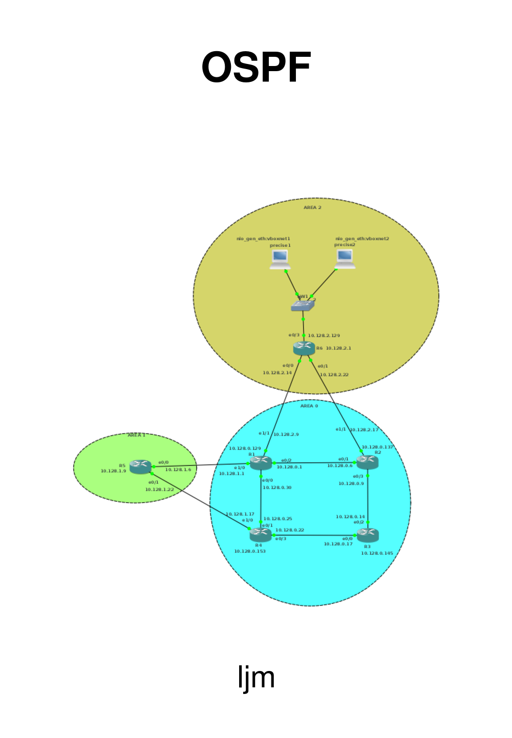
1.5. Areas, Autonomous systems
An Autonomous system is a part of the network that is under control of a single
entity. IANA keeps a list of Autonomous systems that are publicly accessible, but
as long as you don't connect to the Internet, you can use private numbers.
IANA has reserved, for Private Use, a contiguous block of 1023 Autonomous
System numbers from the “16-bit Autonomous System Numbers” registry,
namely 64512 – 65534 inclusive.
IANA has also reserved, for Private Use, a contiguous block of 94,967,295
Autonomous System numbers from the “32-bit Autonomous System Numbers”
registry, namely 4200000000 – 4294967294 inclusive.
OSPF implements a two-level hierachy for areas:
-
Area 0, which is the backbone
-
All other areas
In general, all other areas are connected to the backbone.
We have now seen two types of area:
-
backbone (area 0)
-
standard area
But OSPF is a bit more complicated than that. There are also
-
stub areas
-
totally stubby areas
-
not so stubby areas
and fairly stubby areas, extremely stubby areas, just a bit stubby areas, and ... No, I am
exagerating.
A stub area is an area through which or into which AS external advertisements are not flooded.
This means that you would only be able to access devices within the AS from this type
of area. This is done to reduce the size of the topology database.
Totaly stubby areas takes this one step further by not even allowing LSA type 3; they
are replaced by a default route.
Not So Stubby Areas allow external routes to be flooded within the area. These routes
are leaked into other areas. However, external routes from other areas within the AS
are not flooded into these areas.
You can view the area-types as whether they accept certain types of LSA:
Type 1
|
Type 2
|
Type 3
|
Type 4
|
Type 5
|
Type 7
|
|
Backbone
|
yes
|
yes
|
yes
|
yes
|
yes
|
no
|
Standard
|
yes
|
yes
|
yes
|
yes
|
yes
|
no
|
Stub area
|
yes
|
yes
|
yes
|
no
|
no
|
no
|
Totally Stubby
|
yes
|
yes
|
no
|
no
|
no
|
no
|
Not-so-stubby
|
yes
|
yes
|
yes
|
no
|
no
|
yes
|