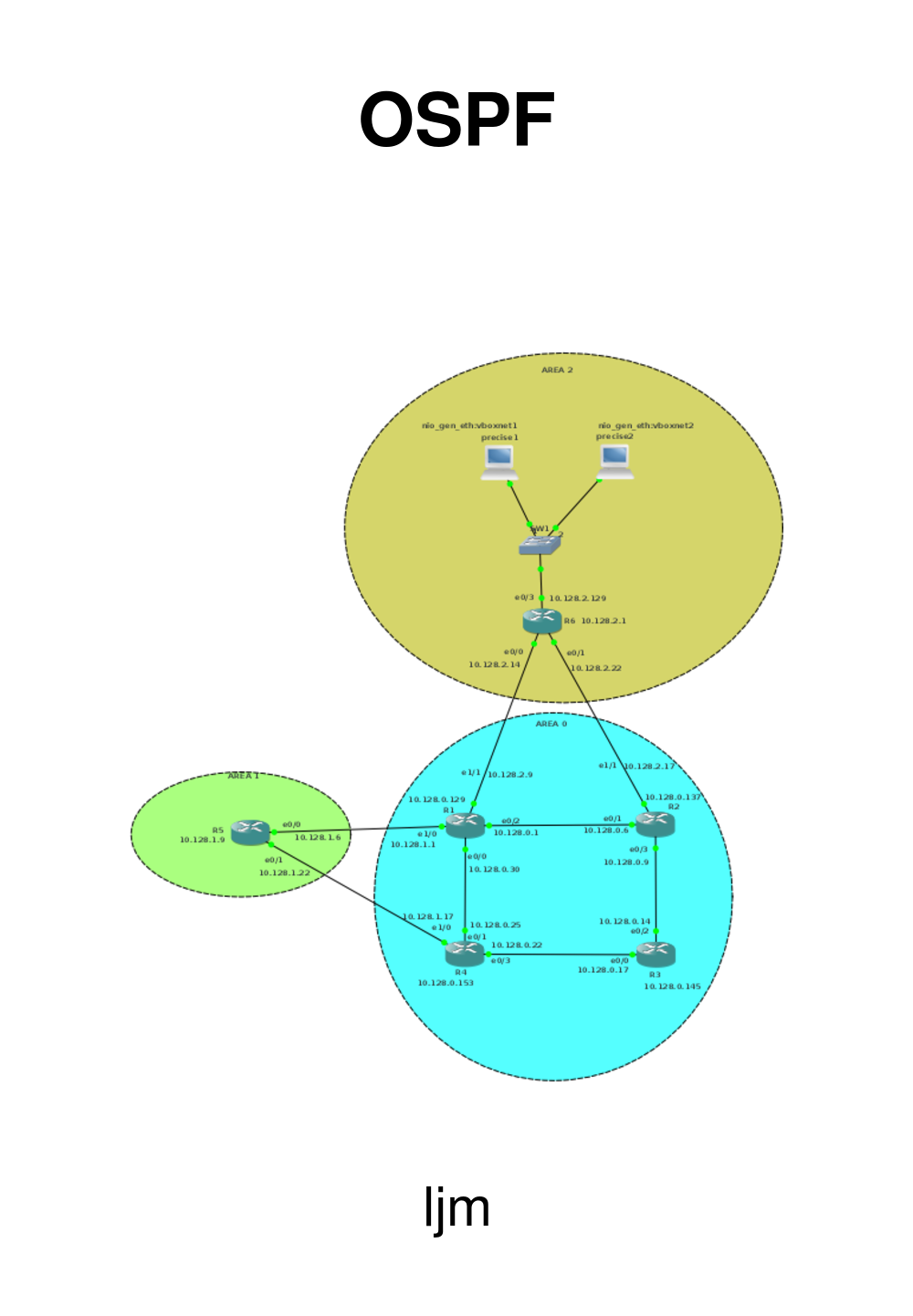
2. Area 0 - the backbone
2.1. Basic network set-up
As discussed, we need an area 0 as backbone for our OSPF. We will be doing
a number of tests here, so we'll create back bone of 4 routers.
We'll use 3600 type routers and put two NM-4E cards in each of them.
We will use the card in slot 0 for the backbone, and the card in slot 1
for connecting the other areas.
We will be using 10.128.0.0/24 for the backbone. I am in general wastefull
in connecting routers in the test environments, using /24 for interconnection
networks, but this time, we'll do some proper calculations.
From
|
To
|
Network
|
Bits
|
Netmask
|
First
|
Last
|
Broadcast
|
R1
|
R2
|
10.128.0.0
|
/29
|
255.255.255.248
|
10.128.0.1
|
10.128.0.6
|
10.128.0.7
|
R2
|
R3
|
10.128.0.8
|
/29
|
255.255.255.248
|
10.128.0.9
|
10.128.0.14
|
10.128.0.15
|
R3
|
R4
|
10.128.0.16
|
/29
|
255.255.255.248
|
10.128.0.17
|
10.128.0.22
|
10.128.0.23
|
R4
|
R1
|
10.128.0.24
|
/29
|
255.255.255.248
|
10.128.0.25
|
10.128.0.30
|
10.128.0.31
|
Because this is the basic set-up, we'll just put the backbone routers in a ring.
The routers will also get a loopback address.
Router
|
Loopback
|
Bits
|
Netmask
|
R1
|
10.128.0.129
|
/29
|
255.255.255.248
|
R2
|
10.128.0.137
|
/29
|
255.255.255.248
|
R3
|
10.128.0.145
|
/29
|
255.255.255.248
|
R4
|
10.128.0.153
|
/29
|
255.255.255.248
|
The network will look like this:

For R1, the basic setup is:
hostname R1
interface Loopback0
 ip address 10.128.0.129 255.255.255.248
!
interface Ethernet0/0
 ip address 10.128.0.30 255.255.255.248
 no shut
!
interface Ethernet0/2
 ip address 10.128.0.1 255.255.255.248
 no shut
!
For R2, the basic setup is:
hostname R2
interface Loopback0
 ip address 10.128.0.137 255.255.255.248
!
interface Ethernet0/1
 ip address 10.128.0.6 255.255.255.248
 no shut
!
interface Ethernet0/3
 ip address 10.128.0.9 255.255.255.248
 no shut
!
For R3, the basic setup is:
hostname R3
interface Loopback0
 ip address 10.128.0.145 255.255.255.248
!
interface Ethernet0/0
 ip address 10.128.0.17 255.255.255.248
 no shut
!
interface Ethernet0/2
 ip address 10.128.0.14 255.255.255.248
 no shut
!
For R4, the basic setup is:
hostname R4
interface Loopback0
 ip address 10.128.0.153 255.255.255.248
!
interface Ethernet0/1
 ip address 10.128.0.25 255.255.255.248
 no shut
!
interface Ethernet0/3
 ip address 10.128.0.22 255.255.255.248
 no shut
!
2.2. OSPF running
Enabling OSPF has the following steps:
-
enable
-
configure terminal
-
router ospf process-id
-
network ip-address wildcard-mask area area-id
-
end
The process-id is uniuqe per router and it allows you to run multiple
OSPF processes in 1 router. Why you would do that I do not understand,
especially not in a real production environment.
The IP-address/wildcard-mask are there to determine which interfaces
should participate in the OSPF routing. Cisco uses the wildcard-mask
to confuse people, because any sensible person would have used the
netmask.
Finaly, the aera-id is 0, because we're setting-up the backbone.
So, it will be:
router ospf 100
network 10.128.0.0 0.0.0.255 area 0
for all the routers in the backbone.
2.3. Verification
First verification is whether all the other addresses in area 0 are pingable.
Next step is to ask the routing table (here for R2):
R2#sh ip route
Codes: C - connected, S - static, R - RIP, M - mobile, B - BGP
       D - EIGRP, EX - EIGRP external, O - OSPF, IA - OSPF inter area
       N1 - OSPF NSSA external type 1, N2 - OSPF NSSA external type 2
       E1 - OSPF external type 1, E2 - OSPF external type 2
        i - IS-IS, su - IS-IS summary, L1 - IS-IS level-1, L2 - IS-IS level-2
       ia - IS-IS inter area, * - candidate default, U - per-user static route
          o - ODR, P - periodic downloaded static route
  Gateway of last resort is not set
       10.0.0.0/8 is variably subnetted, 8 subnets, 2 masks
   C       10.128.0.136/29 is directly connected, Loopback0
   O       10.128.0.129/32 [110/11] via 10.128.0.1, 00:02:00, Ethernet0/1
   O       10.128.0.153/32 [110/21] via 10.128.0.14, 00:02:00, Ethernet0/3
                           [110/21] via 10.128.0.1, 00:02:00, Ethernet0/1
   O       10.128.0.145/32 [110/11] via 10.128.0.14, 00:02:00, Ethernet0/3
   C       10.128.0.8/29 is directly connected, Ethernet0/3
   C       10.128.0.0/29 is directly connected, Ethernet0/1
   O       10.128.0.24/29 [110/20] via 10.128.0.1, 00:02:02, Ethernet0/1
   O       10.128.0.16/29 [110/20] via 10.128.0.14, 00:02:02, Ethernet0/3
   R2#
Luckily, Cisco tells us what the letters mean.
C
|
Directly connected. We see that the loopback address is directly connected and the two ethernet interfaces (e0/3 and e0/1) are directly connected. This is as expected.
|
O
|
A number of routes is learned through OSPF. The router knows about 10,128.0.16/29 through OSPF, and it knows it can reac that address using 10.128.0.14 as the gateway.
|
2.4. Packets
We'll be sniffing on R2 e0/3.
As expected, little traffic goes by in the normal situation. Just some
Hello Packets.

Some more packets arive when we remove a link (R1 to R2). It will not be
instatanous, but after a while:

Let's examine this update:
      LS Update Packet
        Number of LSAs: 1
           LSA-type 1 (Router-LSA), len 60
            .000 0000 0000 0001 = LS Age (seconds): 1
              0... .... .... .... = Do Not Age Flag: 0
              Options: 0x22 ((DC) Demand Circuits, (E) External Routing)
             LS Type: Router-LSA (1)
              Link State ID: 10.128.0.137
             Advertising Router: 10.128.0.137
              Sequence Number: 0x80000024
             Checksum: 0xb13e
This packet comes from the Link State ID 10.128.0.137, which is R2 (Cisco
chooses the IP address of the loopback as ID).
You see that this is an LSA-type 1. In this LSA you will find a list with all the directly
connected links of this router.
So, after R1 to R2 is gone, what does R2 advertise as being connected to?
-
Its loopback address 10.128.0.137; this is a stub
-
Its e0/1 10.128.0.6; this has become a stub when we removed the link to R1
-
The e0/3 network 10.128.0.8/29
And that is exactly what we see:
            Length: 60
               Flags: 0x00
               Number of Links: 3
              Type: Stub     ID: 10.128.0.137    Data: 255.255.255.255 Metric: 1
                 Link ID: 10.128.0.137 - IP network/subnet number
                Link Data: 255.255.255.255
                   Link Type: 3 - Connection to a stub network
                   Number of Metrics: 0 - TOS
                   0 Metric: 1
               Type: Transit  ID: 10.128.0.14     Data: 10.128.0.9      Metric: 10
                   Link ID: 10.128.0.14 - IP address of Designated Router
                   Link Data: 10.128.0.9
                   Link Type: 2 - Connection to a transit network
                   Number of Metrics: 0 - TOS
                   0 Metric: 10
               Type: Stub     ID: 10.128.0.0      Data: 255.255.255.248 Metric: 10
                   Link ID: 10.128.0.0 - IP network/subnet number
                   Link Data: 255.255.255.248
                   Link Type: 3 - Connection to a stub network
                   Number of Metrics: 0 - TOS
                   0 Metric: 10
Ah, but in fact, e0/1 should be a /32, because otherwise we would not be
able to reach R1 E0/2 10.128.0.1, you might say. Well, the resulting
routing table is:
R2>show ip route
Codes: C - connected, S - static, R - RIP, M - mobile, B - BGP
       D - EIGRP, EX - EIGRP external, O - OSPF, IA - OSPF inter area
          N1 - OSPF NSSA external type 1, N2 - OSPF NSSA external type 2
         E1 - OSPF external type 1, E2 - OSPF external type 2
        i - IS-IS, su - IS-IS summary, L1 - IS-IS level-1, L2 - IS-IS level-2
       ia - IS-IS inter area, * - candidate default, U - per-user static route
          o - ODR, P - periodic downloaded static route
  Gateway of last resort is not set
       10.0.0.0/8 is variably subnetted, 8 subnets, 2 masks
   C       10.128.0.136/29 is directly connected, Loopback0
   O       10.128.0.129/32 [110/31] via 10.128.0.14, 00:05:17, Ethernet0/3
   O       10.128.0.153/32 [110/21] via 10.128.0.14, 00:05:17, Ethernet0/3
   O       10.128.0.145/32 [110/11] via 10.128.0.14, 00:05:17, Ethernet0/3
   C       10.128.0.8/29 is directly connected, Ethernet0/3
   C       10.128.0.0/29 is directly connected, Ethernet0/1
   O       10.128.0.24/29 [110/30] via 10.128.0.14, 00:05:17, Ethernet0/3
   O       10.128.0.16/29 [110/20] via 10.128.0.14, 00:05:18, Ethernet0/3
So, no, it does not become a /32 and yes. the ping to 10.120.0.1 fails:
R2>ping 10.128.0.1
Type escape sequence to abort.
Sending 5, 100-byte ICMP Echos to 10.128.0.1, timeout is 2 seconds:
.....
Success rate is 0 percent (0/5)
R2>
Which is as expected.