
2. The network
2.1. Set-up
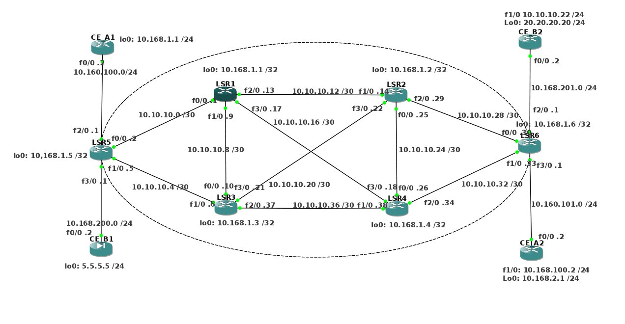
Because the original lab is no longer available, I added the router configs in
the last chapters. The network is as depicted below.
Perhaps a simpler way to see the connected interfaces is:

Router
|
lo0
|
f0/0
|
f1/0
|
f2/0
|
f3/0
|
LSR1
|
10.168.1.1
|
10.10.10.1
|
10.10.10.9
|
10.10.10.13
|
10.10.10.17
|
LSR2
|
10.168.1.2
|
10.10.10.25
|
10.10.10.14
|
10.10.10.29
|
10.10.10.22
|
LSR3
|
10.168.1.3
|
10.10.10.10 10.10.10.16
|
10.10.10.37
|
10.10.10.21
|
|
LSR4
|
10.168.1.4
|
10.10.10.26
|
10.10.10.38
|
10.10.10.34
|
10.10.10.18
|
LSR5
|
10.168.1.5
|
10.10.10.2
|
10.10.10.5
|
10.160.100.1
|
10.168.200.1
|
LSR6
|
10.168.1.6
|
10.10.10.30
|
10.10.10.33
|
10.168.201.1
|
10.160.101.1
|
CE_A1
|
10.168.1.1
|
10.160.100.2
|
|||
CE_A2
|
10.168.2.1
|
10.160.101.2
|
10.168.2.1
|
||
CE_B1
|
5.5.5.5
|
10.168.200.2
|
|||
CE_B2
|
10.10.10.10
|
10.168.201.2
|
10.10.10.22
|
A verification proves that it is indeed possible to ping the neighbouring routers.
OSPF will route everything through the LSR-routers, so all addresses can be pinged.
Another verification is
show ip route
:
LSR1#show ip route
Codes: C - connected, S - static, I - IGRP, R - RIP, M - mobile, B - BGP
       D - EIGRP, EX - EIGRP external, O - OSPF, IA - OSPF inter area
       N1 - OSPF NSSA external type 1, N2 - OSPF NSSA external type 2
       E1 - OSPF external type 1, E2 - OSPF external type 2, E - EGP
       i - IS-IS, L1 - IS-IS level-1, L2 - IS-IS level-2, ia - IS-IS inter area
       * - candidate default, U - per-user static route, o - ODR
       P - periodic downloaded static route
Gateway of last resort is not set
     10.0.0.0/8 is variably subnetted, 16 subnets, 2 masks
C       10.10.10.8/30 is directly connected, FastEthernet1/0
C       10.10.10.12/30 is directly connected, FastEthernet2/0
C       10.10.10.0/30 is directly connected, FastEthernet0/0
O       10.10.10.4/30 [110/2] via 10.10.10.2, 00:27:32, FastEthernet0/0
                      [110/2] via 10.10.10.10, 00:27:32, FastEthernet1/0
O       10.10.10.24/30 [110/2] via 10.10.10.18, 00:27:32, FastEthernet3/0
                       [110/2] via 10.10.10.14, 00:27:32, FastEthernet2/0
O       10.10.10.28/30 [110/2] via 10.10.10.14, 00:27:32, FastEthernet2/0
C       10.10.10.16/30 is directly connected, FastEthernet3/0
O       10.10.10.20/30 [110/2] via 10.10.10.10, 00:27:32, FastEthernet1/0
                       [110/2] via 10.10.10.14, 00:27:32, FastEthernet2/0
O       10.10.10.32/30 [110/2] via 10.10.10.18, 00:27:32, FastEthernet3/0
O       10.10.10.36/30 [110/2] via 10.10.10.18, 00:27:46, FastEthernet3/0
                       [110/2] via 10.10.10.10, 00:27:46, FastEthernet1/0
O       10.168.1.3/32 [110/2] via 10.10.10.10, 00:27:46, FastEthernet1/0
O       10.168.1.2/32 [110/2] via 10.10.10.14, 00:27:46, FastEthernet2/0
C       10.168.1.1/32 is directly connected, Loopback0
O       10.168.1.6/32 [110/3] via 10.10.10.18, 00:27:46, FastEthernet3/0
                      [110/3] via 10.10.10.14, 00:27:46, FastEthernet2/0
O       10.168.1.5/32 [110/2] via 10.10.10.2, 00:27:46, FastEthernet0/0
O       10.168.1.4/32 [110/2] via 10.10.10.18, 00:27:46, FastEthernet3/0
LSR1#
It may be, that, when you use the configs, CEF will be enabled, but
you need to start MPLS on the specific interfaces.
For LSR1, LSR2, LSR3 and LSR4, cut and paste this:
enable
config t
int f0/0
mpls ip
int f1/0
mpls ip
int f2/0
mpls ip
int f3/0
mpls ip
for LSR5 and LSR6:
enable
conf t
int f0/0
mpls ip
int f1/0
mpls ip
To verify that everything works, start a ping on LSR5 to the loopback address of LSR6
and start a capture on wireshark. To make sure everything goes over the captured
wire, you might want to shut-down some routers. In the trace below, you'll see
only the echo requests, not the replies. The replies took aother route through the
MPLS cloud.
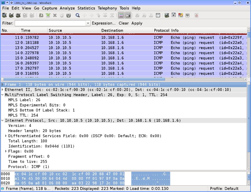
So what we see here is an echo request in MPLS. MPLS puts a header in front of the
packet. This header allows faster routing through the MPLS cloud.
2.2. MPLS tests
So now MPLS works. Socketready now goes on to configuring the
customer VPNs. But first, some exploration of the MPLS
needs to be done.
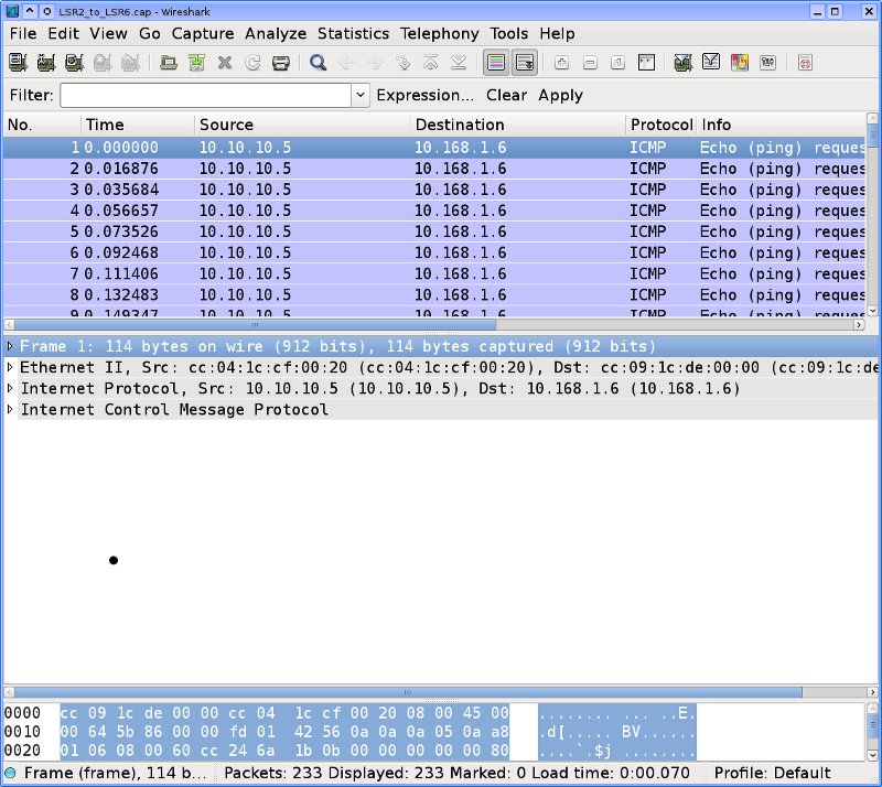
2.2.1. Where did our ping go?
Earlier, we saw that the echo request from LSR5 to LSR6 went over the link between
LSR1 and LSR2, but we did not see any replies. So, the replies must follow another
route. And indeed: the replies go over LSR4.

Notice, that the MPLS label is different. This is exactly what we expect.
2.2.2. Remove label at the last hop
Apparently, MPLS removes the MPLS label for the last hop.
This is consistent behaviour, as you can see for the replies:

Apparently, this is the result of a feature called PHP (Penultimate Hop Popping).
If I understand it correctly, the last hop would be the one in LSR6 from f0/0 to the
loopback interface.
If you ping between two CE routers, everything in the MPLS-cloud will have an MPLS header.