
2. The network
As said, our network differs a bit from Packetlife's. Being network-people, Packetlife
likes to use loopback interfaces, but we have complete virtual machines, so why settle
for less?
2.1. Two customers MPLS network
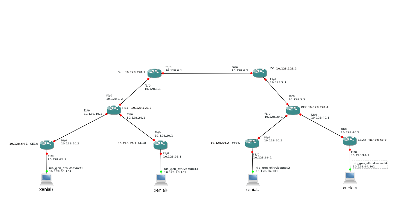
As image I used c3660-jk9o3s-mz.124-17.bin and I put fast-ethernet cards in all slots.
The Vagrantfile is:
# -*- mode: ruby -*-
# vi: set ft=ruby :
# Vagrantfile API/syntax version. Don't touch unless you know what you're doing!
# Vagrant.configure("2") do |config|
#   config.vm.box = "minimal/xenial64"
#   end
#
VAGRANTFILE_API_VERSION = "2"
Vagrant.configure(VAGRANTFILE_API_VERSION) do |config|
	config.vm.define :xenial1 do |t|
		t.vm.box = "ubuntu/xenial64"
		# t.vm.box_url = "file://links/virt_comp/vagrant/boxes/xenial64.box"
		t.vm.provider "virtualbox" do |prov|
			prov.customize ["modifyvm", :id, "--nic2", "hostonly", "--hostonlyadapter2", "vboxnet1" ]
		end
		t.vm.provision "shell", path: "./setup.xenial1.sh"
	end
	config.vm.define :xenial2 do |t|
		t.vm.box = "ubuntu/xenial64"
		#t.vm.box_url = "file://links/virt_comp/vagrant/boxes/xenial64.box"
		t.vm.provider "virtualbox" do |prov|
			prov.customize ["modifyvm", :id, "--nic2", "hostonly", "--hostonlyadapter2", "vboxnet2" ]
		end
		t.vm.provision "shell", path: "./setup.xenial2.sh"
	end
	config.vm.define :xenial3 do |t|
		t.vm.box = "ubuntu/xenial64"
		#t.vm.box_url = "file://links/virt_comp/vagrant/boxes/xenial64.box"
		t.vm.provider "virtualbox" do |prov|
			prov.customize ["modifyvm", :id, "--nic2", "hostonly", "--hostonlyadapter2", "vboxnet3" ]
		end
		t.vm.provision "shell", path: "./setup.xenial3.sh"
	end
	config.vm.define :xenial4 do |t|
		t.vm.box = "ubuntu/xenial64"
		#t.vm.box_url = "file://links/virt_comp/vagrant/boxes/xenial64.box"
		t.vm.provider "virtualbox" do |prov|
			prov.customize ["modifyvm", :id, "--nic2", "hostonly", "--hostonlyadapter2", "vboxnet4" ]
		end
		t.vm.provision "shell", path: "./setup.xenial4.sh"
	end
	config.vm.define :xenial5 do |t|
		t.vm.box = "ubuntu/xenial64"
		#t.vm.box_url = "file://links/virt_comp/vagrant/boxes/xenial64.box"
		t.vm.provider "virtualbox" do |prov|
			prov.customize ["modifyvm", :id, "--nic2", "hostonly", "--hostonlyadapter2", "vboxnet5" ]
		end
		t.vm.provision "shell", path: "./setup.xenial5.sh"
	end
end
On our P and PE routers, we've enabled MPLS. As a default, LDP is enabled.
It runs between the loopback interfaces of the routers.
The interfaces can connect because we run OSPF on the MPLS-routers.
You can see what OSPF does:
P1#sh ip OSPF DATABASE
            OSPF Router with ID (10.128.128.1) (Process ID 1)
                Router Link States (Area 0)
Link ID         ADV Router      Age         Seq#       Checksum Link count
10.128.128.1    10.128.128.1    20          0x80000003 0x000BAE 3
10.128.128.2    10.128.128.2    20          0x80000003 0x004D66 3
10.128.128.3    10.128.128.3    23          0x80000002 0x00F1E9 2
10.128.128.4    10.128.128.4    24          0x80000002 0x000EC8 2
                Net Link States (Area 0)
Link ID         ADV Router      Age         Seq#       Checksum
10.128.0.2      10.128.128.2    25          0x80000001 0x000186
10.128.1.2      10.128.128.3    23          0x80000001 0x00F98A
10.128.2.2      10.128.128.4    25          0x80000001 0x00017F
and on the wire between P1 and P2, you'll see the OSPF packets:

You will also notice that the CE-routers are not in the OSPF database.
2.2. Routing on the PE
We defined VRFs on the PE routers for each customer:
ip vrf Customer_A
 rd 65000:1
 route-target export 65000:1
 route-target import 65000:1
 route-target import 65000:99
!
ip vrf Customer_B
 rd 65000:2
 route-target export 65000:2
 route-target import 65000:2
 route-target import 65000:99
We used the same route distinguisher (RD) on both PE routers. Best practice is to use a different RD
on each VRF. RDs are used to make routes globally unique. We use the same RD on both PE routers, because
we are sure that the routes that are advertised are already unique per customer (A and B). If the network
behind the CE routers is more dynamic, do not use the same RDs.
Route-targets and route-distinguishers are used to define the separate customers.
With the route-targets we can define which VRF sees which VRF.
We used the format :; customer 99 is for later use.
The VRFs are defined on the interfaces that connect the CE-routers:
!
interface FastEthernet1/0
 ip vrf forwarding Customer_A
 ip address 10.128.10.1 255.255.255.0
 ip ospf 2 area 0
 duplex auto
 speed auto
!
interface FastEthernet2/0
 ip vrf forwarding Customer_B
 ip address 10.128.20.1 255.255.255.0
 ip ospf 3 area 0
 duplex auto
 speed auto
!
And you can see that it works:
PE1#sh ip vrf interfaces
Interface              IP-Address      VRF                              Protocol
Fa1/0                  10.128.10.1     Customer_A                       up
Fa2/0                  10.128.20.1     Customer_B                       up
The next step
is the routing of client traffic.
router bgp 65000
 bgp log-neighbor-changes
 neighbor 10.128.128.4 remote-as 65000
 neighbor 10.128.128.4 update-source Loopback0
 neighbor 10.128.128.5 remote-as 65000
 neighbor 10.128.128.5 update-source Loopback0
 no auto-summary
 !
 address-family vpnv4
  neighbor 10.128.128.4 activate
  neighbor 10.128.128.4 send-community extended
  neighbor 10.128.128.5 activate
  neighbor 10.128.128.5 send-community extended
 exit-address-family
 !
 address-family ipv4 vrf Customer_B
  redistribute ospf 3 vrf Customer_B
  no synchronization
 exit-address-family
 !
 address-family ipv4 vrf Customer_A
  redistribute ospf 2 vrf Customer_A
  no synchronization
 exit-address-family
!
So what does that mean?
router bgp 65000
neighbor 10.128.128.4 remote-as 65000
adds the other PE router to the BGP table. Our autonomous system (AS) is 65000, which is
often used for private networks.
neighbor 10.128.128.4 update-source Loopback0
we define the loopback interface as the operational interface for the TCP connections.
address-family vpnv4
 neighbor 10.128.128.4 activate
 neighbor 10.128.128.4 send-community extended
 neighbor 10.128.128.5 activate
 neighbor 10.128.128.5 send-community extended
 exit-address-family
This defines the VPNs. The RDs make the routes unique, even if customers use the
same address space (e.g. 10.0.0.0/8). We've seen the RDs in the VRF definition above.
the router 10.128.128.5 is for later use.
 address-family ipv4 vrf Customer_B
  redistribute ospf 3 vrf Customer_B
  no synchronization
 exit-address-family
 address-family ipv4 vrf Customer_A
  redistribute ospf 2 vrf Customer_A
  no synchronization
 exit-address-family
finaly allows OSPF with the CE routers.
It is important to see that the complete separation of customers is handled by the provider.
This has some security implications. If you are a provider, you will need to be in complete
control of the separation to fulfill your contractual obligations. As a client, you will want
to make sure that your provider takes care of that separation. This can be done through contracts,
if you trust your provider enough, or through read rights on the PE-routers. And that could
be problematic. A solution would be to have a right to audit, as is often provided by the
contracts. You might also do some security monitoring here; IDS could be a valid requirement.
2.3. The resulting network
Now we can ping between xenial1/xenial2 and xenial3/xenial4, but not from xenial1 to xenial3.
As an example:
ljm[MPLS_common_services]$ vagrant ssh xenial1 -c 'ping -c2  10.128.66.101'
PING 10.128.66.101 (10.128.66.101) 56(84) bytes of data.
64 bytes from 10.128.66.101: icmp_req=1 ttl=58 time=142 ms
64 bytes from 10.128.66.101: icmp_req=2 ttl=58 time=118 ms
--- 10.128.66.101 ping statistics ---
2 packets transmitted, 2 received, 0% packet loss, time 1001ms
rtt min/avg/max/mdev = 118.239/130.381/142.524/12.147 ms
Connection to 127.0.0.1 closed.
ljm[MPLS_common_services]$ vagrant ssh xenial1 -c 'ping -c2  10.128.93.101'
PING 10.128.93.101 (10.128.93.101) 56(84) bytes of data.
From 10.128.65.1 icmp_seq=1 Destination Host Unreachable
From 10.128.65.1 icmp_seq=2 Destination Host Unreachable
--- 10.128.93.101 ping statistics ---
2 packets transmitted, 0 received, +2 errors, 100% packet loss, time 1001ms
Connection to 127.0.0.1 closed.
ljm[MPLS_common_services]$ vagrant ssh xenial1 -c 'traceroute  10.128.66.101'
traceroute to 10.128.66.101 (10.128.66.101), 30 hops max, 60 byte packets
 1  10.128.65.1 (10.128.65.1)  14.152 ms  14.034 ms  13.952 ms
 2  10.128.10.1 (10.128.10.1)  34.125 ms  34.014 ms  33.926 ms
 3  10.128.1.1 (10.128.1.1)  115.482 ms  115.421 ms  115.344 ms
 4  10.128.0.2 (10.128.0.2)  115.265 ms  115.189 ms  115.111 ms
 5  10.128.30.1 (10.128.30.1)  94.729 ms  94.675 ms  94.598 ms
 6  10.128.30.2 (10.128.30.2)  114.787 ms  103.218 ms  103.113 ms
 7  10.128.66.101 (10.128.66.101)  123.240 ms  117.791 ms  117.928 ms
Connection to 127.0.0.1 closed.
What we see in the traceroute is that all the MPLS routers are seen. This can
be hidden with
no mpls propagate-ttl.
See
https://www.cisco.com/c/en/us/support/docs/multiprotocol-label-switching-mpls/mpls/26585-mpls-traceroute.html
for details on the traceroute.